Contact me
Copyright© 2025 by Beckford Technologies. All rights reserved. Page revised on 08 Apr 2025.

| Trouble Shooting |
| Design Modifications |
| Compliance Assistance |
| Low Power Optimization |
| Battery Charging |
| Antenna Integration |
| Simulation |
| Testing |
| PCB Layout |
| Analog Design |
| RF and Wireless |
| Precision Sensing |
Contact me
Copyright© 2025 by Beckford Technologies. All rights reserved. Page revised on 08 Apr 2025.
FCC Part 15 Failure | Cellular Modem Integration | Battery Life Optimization
These examples are drawn from the over 50 projects I've done in the last 20 years. They represent an accumulation of experience acquired in the designing, building, and testing of devices that must meet real-world performance, manufacturability, regulatory, and cost requirements.
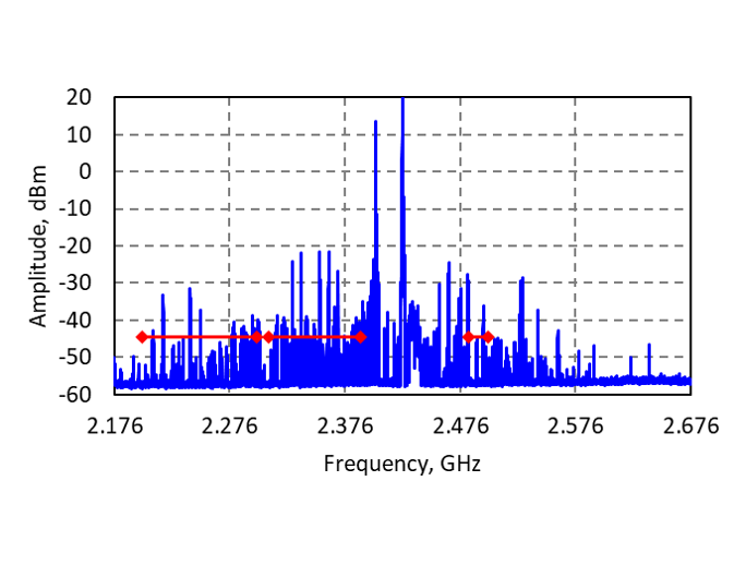
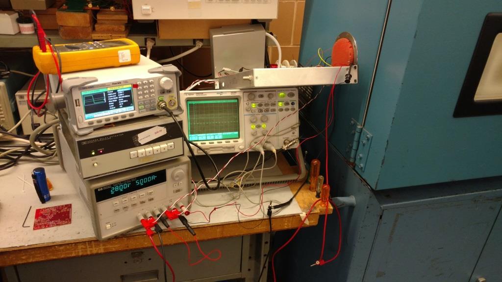
A client had trouble passing FCC Part 15 tests due to conducted spurious emissions, both in-band and near band. The device was a Bluetooth beacon which operated at up to +25 dBm output power. The spurious could also be seen at lower power settings although those did not violate the FCC requirement. Nevertheless, such spurious output was unusual from any manufacturer.
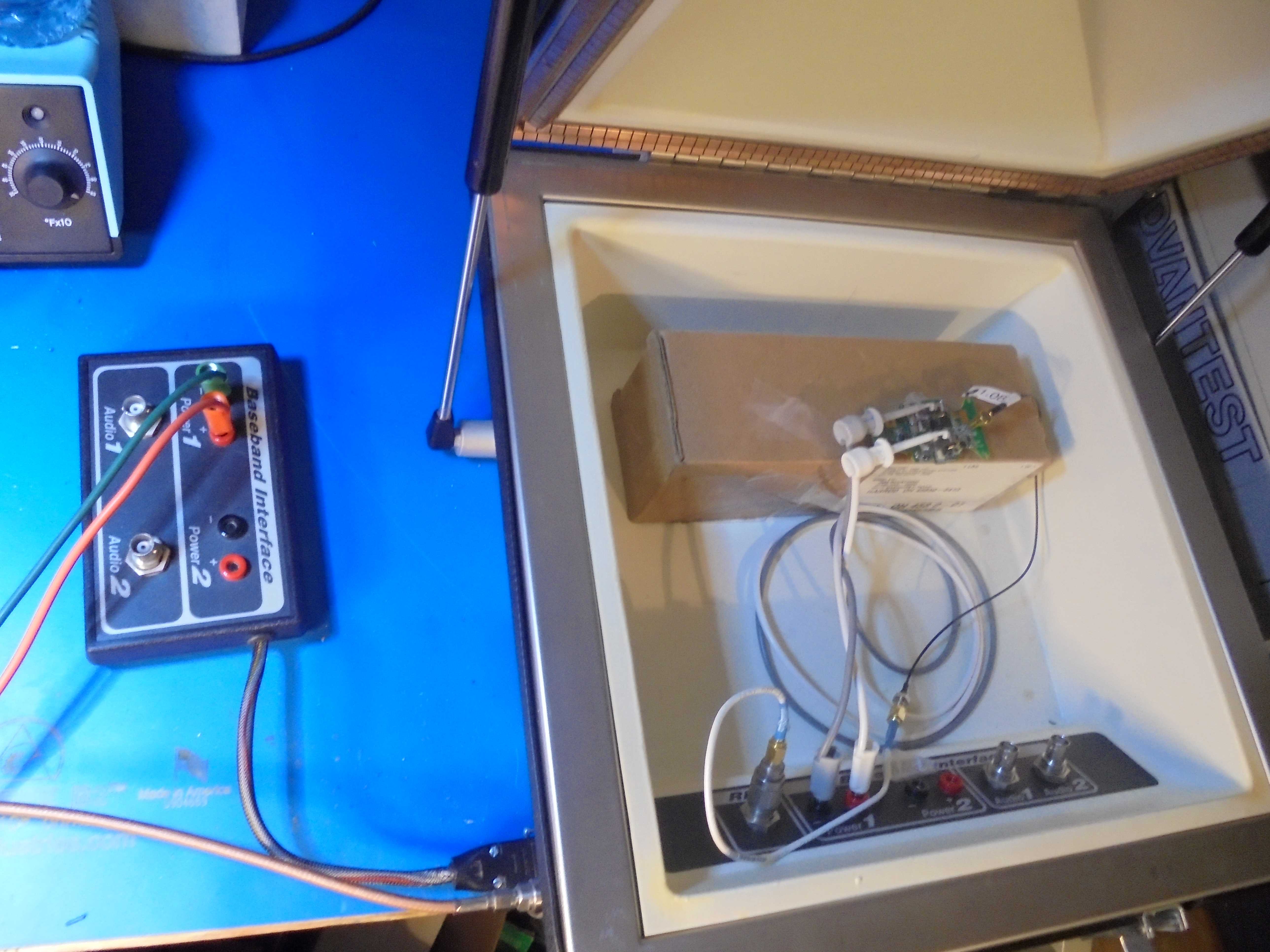
An initial examination and evaluation looked at the possiblility of external noise pickup using an isolation chamber. Other possible sources such as internal switching power supply noise and improper signal routing on the PCB were also considered. The audible beeper was disconnected, the on-board vibratory motor was also disconnected, and the case of the crystal was grounded. None of these measures resulted in any evidence that they were the source of the spurs.
Working closely with the client's internal firmware team, multiple versions of the firmware were created to defeat various product features and disable external hardware. Binary files were passed between the firmware team and Beckford Technologies using secure cloud storage which facilitated multiple turn-arounds each day. After several days, the problem was found and documented. During the tranmission time slot, an interrupt was occurring at which time the ADC internal to the processor was activated to take several measurements. Further investigation revealed that is was NOT the ADC, but rather, the interrupt system of the chip. With this knowledge in hand, the firmware team was able to quickly resolve the issue by disabling the interrupt system and using a polling method. With this firmware change, Beckford Technologies was able to pre-test the conducted emissions giving very high confinence that the product would easily pass FCC requirements. Subsequent testing by a certified lab proved this out and the product met all requirements.
Several clients have required cellular connectivity for their products. This connection allows the product to be field deployed nearly anywhere in the world without any other client supplied physical infrastructure or assets. Readily available modules simplify the hardware design and provide a standard 50 Ohm antenna connection. All that is needed to complete the electrical design is an appropriate antenna and a matching circuit.
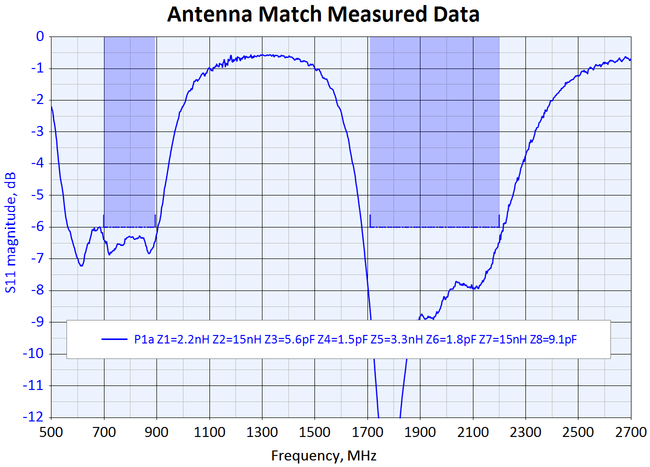
This requires knowledge of the bands that are used as well as all the worlwide location where the product could be deployed. Unlike a simple 915 MHz or 2.4 GHz ISM radio which is typically one band, cellular's multiple bands can range from 600 MHz to 5.2 GHz. This requires an antenna that can operate efficiently on all these bands as well the appropriate multi-band matching network.
One simple solution is a flexible printed circuit (FPC) antenna. These are typically matched to 50 Ohms and include a cabled section which allows the antenna to be placed away from the PC board which limits the board's effect on performance. For applications which will operate on only a couple of the cellular bands, they provide a degree of flexibility in mounting and don't require any PC board real estate.
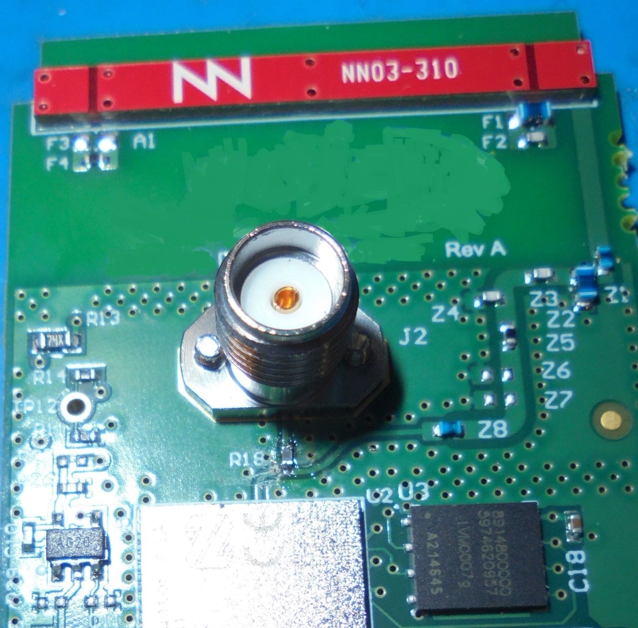
A more production friendly solution is to use a chip antenna such as supplied by Ignion. This has been used on two projects and has proven successful. The matching circuit becomes more complex but the manufacturer computes initial values of the components. Final antenna matching then is a matter of making measurements using a vector network analyzer (VNA) to match the cellular module being used. The addition of an external connector complicates the matching and can introduce error, so an on-board connector is used for the connection. This connection is easy to model and thus can be removed readily from the matching.
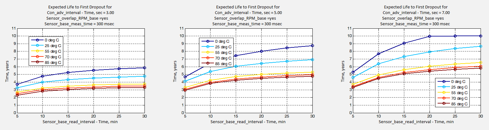
A client required an IoT industrial sensor that would be buried within a machine. It had several temperature sensors including two infrared sensors. It also included a fluid leak detector, an RPM sensor, a humidity sensor, and a vibration sensor. The processor incorporated a Bluetooth radio for communications with a custom smartphone app. With this number of sensors and frequent communications, power management was critical. The sensor needed to operate over the temperature range of 0 °C to +85 °C with much of the expected operation occurring near the high end of that range.
Power management required close coordination with the software team. Initially, it was discovered that not all of the advertised power saving features of the processor were fully supported by the manufacturer so job one was a careful measurement of the processor current consumption in its various modes which allowed the software team to define their own low power and sleep states in order to achieve the desired battery life.
Additionally, when powering this many sensors, the inrush current to charge the bulk capacitors exceeded the battery pulse capability. A slow turn-on and turn-off switch was designed to mitigate this, the firmware then incorporating the necessary delays.
Once powered on, each sensor had its own additional delay until it could produce valid readings. Again, this feedback was given to the firmware team so that sensors were not powered up and waiting, wasting power. Finally, the actual current draw over temperature was measured for each sensor and an accurate estimation of battery life made using MATLAB® which allowed the client to understand the trade-offs between battery life and the sensor reading rate, advertising interval, and the temperature. This permitted accurate communication of the expected battery life to the marketing team so that they could set customer expectations.